Security

Airflow, Azure and OAuth

NOTE: This is an incomplete article – I will continue to publish more as I can. I have provided the needed code for “webserver_config.py” I have not included information for the “App Registration” in Azure.

This article stems from me not finding enough information, in one place, pertaining to authenticating to Apache Airflow leveraging OAuth and Azure.

I was able to piece what I needed together using documentation from different sources: GitHub, Flask, Apache, etc.

My hope is that this article provide you with the information needed to get authentication functional in your environment.

If you are using the Apache Airflow public helm chart – this is the code that will help get you going. This can be added to your “values.yaml” or “overrides.yaml” file.  If not using a helm chart, then add the python portion – starting with the first “from” to the end of the code block and add it to your “webserver_config.py” file.

webserver:
  service:
    type: NodePort
  webserverConfig: |
    
    from airflow.www.security import AirflowSecurityManager
    import logging
    from typing import Dict, Any, List, Union
    from flask_appbuilder.security.manager import AUTH_OAUTH
    import os

    # basedir = os.path.abspath(os.path.dirname(__file__))

    WTF_CSRF_ENABLED = True
    # SQLALCHEMY_DATABASE_URI = conf.get("core", "SQL_ALCHEMY_CONN")

    AUTH_TYPE = AUTH_OAUTH
    AUTH_ROLES_SYNC_AT_LOGIN = True
    PERMANENT_SESSION_LIFETIME = 1800 # force users to reauth after inactivity period time in seconds
    AUTH_USER_REGISTRATION = True
    AUTH_USER_REGISTRATION_ROLE = "Public"

    class AzureRoleBasedSecurityManager(AirflowSecurityManager):
        def _get_oauth_user_info(self, provider, resp):
            if provider == "azure":
                me = self._azure_jwt_token_parse(resp["id_token"])
                return {
                    "id": me["oid"],
                    "username": me["upn"],
                    "name": me["name"],
                    "email": me["upn"],
                    "first_name": me["given_name"],
                    "last_name": me["family_name"],
                    "role_keys": me["roles"],
                }
            return {}
        oauth_user_info = _get_oauth_user_info

    SECURITY_MANAGER_CLASS = AzureRoleBasedSecurityManager

    # In order of least permissive - default is "Public" - see AUTH_USER_REGISTRATION_ROLE
    AUTH_ROLES_MAPPING = {
      "Public": ["Public"],
      "Viewer": ["Viewer"],
      "User": ["User"],
      "Op": ["Op"],
      "Admin": ["Admin"],
    }

    OAUTH_PROVIDERS = [
      {
        "name": "azure",
        "icon": "fa-windows",
        "token_key": "access_token",
        "remote_app": {
          "client_id": "<from Azure>",
          "client_secret": "<from Azure>",
          "api_base_url": "https://login.microsoftonline.com/<from Azure>/oauth2",
          "client_kwargs": {
            "scope": "User.read name preferred_username email profile upn",
            "resource": "<from Azure>"},
          "access_token_url": "https://login.microsoftonline.com/<from Azure>/oauth2/token",
          "authorize_url": "https://login.microsoftonline.com/<from Azure>/oauth2/authorize",
          "request_token_url": None,
        },
      },
    ]

Cisco ACL — Dedicated Internet Edge Drop Device

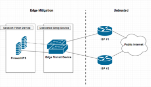
A dedicated drop device is a network appliance, usually a router or L3 switch that sites at the very edge of your network infrastructure. Beyond the firewall, and usually acts a as either layer 2 or 3 transit devices for your ISP interconnect uplinks for public or untrusted segments. Distinguishing a dedicated drop devices in your infrastructure interconnected chain of paths can enhance and offload many irrelevant packet transactions from ever hitting your Firewall mitigation appliances. The thought around this approach is to remove processing cycles away from your more expensive security appliances such as firewalls or IPS, allowing said devices to dedicate their efforts toward more complicated session and/or application driven attacks.

Continue reading…

Security Through Obscurity

Security Through Obscurity?

This my first ever post and I feel it’s a pertinent one to mention.

What is it and why is it bad?
Security through obscurity can be said to be bad because it often implies that the obscurity is being used as the principal means of security. Obscurity is fine until it is discovered, but once someone has worked out your particular obscurity, then your system is vulnerable again. [source: https://en.wikipedia.org/wiki/Security_through_obscurity]

Security is an often overlooked topic in organizations. I’ve heard many different arguments for why things were configured a certain way. Once thing that stands is security through obscurity should never be overlooked. Things are always secure, until they’re not. You should never expose something publicly that is not meant to be exposed publicly.

Continue reading…

The Remote Access VPN Battle — SSL vs IPSec VPN

I’ve recently posted two articles covering two different VPN connection methods. SSL Remote VPN and IPSec Remote VPN via Cisco ASA security applicance. In the article I promised I would go thru and do a deteail compare and contrast of them. So Let’s get start!!

As promised here is the follow up post I mentioned here regarding setting up an Cisco AnyConnect remote access. Luckly the process is very similar to a remote access IPSec tunnel in the previous article with a few exceptions. Lets work through the differences between Cisco AnyConnect and a standard remote access IPSec Client VPN.

ComparisonSSL Remote VPNIPSec Remote VPN
Cost$$ per Connection, SSL certificate costsUsually none, no SSL certificate costs
CapacitySeats limited to licensingLimited to Crypto Hardware
PerformanceSSL with DTLS = Very FastIPsec without NAT-T = fast
VulnerabilitySSL vulnerabilties released frequentlyIPSec requires pre-shared key
RequirementsSSL requires TCP 443, DTLS requires UDP 443IPSec requires IP Protcol 50 (ESP) and UDP 500(IKEv1), NAT-T requires UDP 4500
Connection ConsiderationsSSL requires TCP 443 outbound for clientsIPSec requires both Layer 3 and Layer 4 protocols

NOTE: The table here is a quick reference when comprising SSL remote VPN with IPSec remote VPN. There are many things to consider when choosing between the two. SSL VPN is newer than IPSec, however the answer on which is better is not so straight forward.

IPSec remote VPN utilizes a variety of protocols and ports to form a successful tunnel. If you remember from my article on IPSec and NAT-Traversal, port requirements are UDP 500 for IKEv1 exchange, IP Protocol 50 for ESP communication, and if negotiated UDP 4500 for NAT-T. Most of the time these ports and protocols will not be allowed access outbound to the Internet. For instance, many guest networks like hotels and conferences only allow web browsable ports, such as 80(HTTP) and 443(HTTPS) outbound. That is a lot of firewall exceptions to establish an IPSec remote VPN.

SSL remote VPN introduces many connection and scalability improvements, making remote VPN functionality easier for the end user. SSL remote VPN solves the IPSec issues of a opening ports to establish a VPN session. Remote users no longer connect differently depending on where they are nor do they need to know how they are connected to the Internet, no fancy ports need to be opened, no issues with NAT-Traversal, etc. SSL remote VPN uses a very common trusted port for communication TCP 443 (and UDP 443, more on that later). This port is 99% of the time open to communicate with the Internet web sites. Using a commonly allowed port eliminates the issues seen with IPSec when establishing a VPN.

The trade-off, SSL remote VPN communicates via SSL/TLS. As stated this requires TCP, which is a stateful transport protocol. The issue arises when you have a remote host operating an application that uses TCP as well, such as web browser or Remote Desktop Connection. The scenario is now TCP on top of TCP, resulting in heavy overhead. Imaging the following scenario, you have a SSL remote VPN host connected, they then open a RDP session to a server on your network. So far so good. Now what happens when either the RDP session or the SSL remote VPN session requires a re-transmission because of connectivity problems. TCP re-transmission storms. Both the VPN session and RDP session will require re-transmissions, generating heavy overhead. Now this is not to say that either session will not recover, cause they will unless the connection is completely severed, TCP will do its job. Datagram Transport Layer Security(DTLS) to the rescue!!!

Datagram Transport Layer Security (DTLS)

DTLS is the savior and its what makes SSL client VPNs a very competitive remote access VPN technology. DTLS was designed to secure traffic similar to TLS, but without having to rely so heavily on the underlying TCP transport. TLS relies on TCP to guarantee delivery in the event of message fragmentation, message reordering, and message loss. So getting ride of any one of those TCP features will break the TLS crypto logic.  DTLS solution to these issues is as follows:

  • Message Fragmentation — Fragmentation occurs when a packet datagram is too large to fit within an MTU (usually 1500bytes’ish). Fragmentation is detected and handled by the transport technology (TCP/UDP). TCP has mechanisms built in to solve this while UDP does not. DTLS solves this issue by introducing its own fragmentation offset and length value in the DTLS message itself. This ensure that both ends of the communication are provided fragmentation information regardless of the underlying transport.
  • Message Reordering — Reordering occurs for several reasons, a common reason is delayed delivery of the underlying network. Reordering isn’t a huge issue for transport technologies like TCP because it uses sequence numbering to ensure the original data is reassembled properly. TLS requires the sequential delivery of packets to preform it’s crypto logic, meaning TLS needs the previous packet to be able to decrypt the next packet N+1. DTLS solves this by adding it’s own sequence numbering to the application, allowing it to not be dependent on the underlying transport technology.
  • Message Loss — Packet loss occurs when a packet in a data stream never reaches its destination in a certain period of time. Message loss is handled very similar to Message Recording. For TLS and it’s TCP transport, re-transmissions are triggered for lost packets when sequence numbering doesn’t compute correctly for a agreed upon window. DTLS fixes this by adding a simple re-transmission timer to it’s application logic, thereby allowing it to re-transmit packets without relying on the transport protocol.

Keep in mind that DTLS built-in functionality of these usually transport specific recovery mechanisms creates the need for additional RAM/memory on the server-side. Another cool fact is most of these “fixes” come from IPSec ESP technology! See RFC4347 for more information.

Helpful links:

Cisco AnyConnect SSL/TLS Trustpoint

I wanted to put together a quick tutorial for setting up a Cisco ASA – AnyConnect with SSL/TLS. I’ve done it a few times and I always have to re-lookup each step and the order in which to do it, so why not make a quick post about it to remember!

Optional: Destroy Current Trustpoint

You will have to destroy or clear out the current trustpoint if it already exists. This must be done if you are going to re-generate the key, which is best practice when renewing a Certificate due to expiration or one that has been compromised.

asa01(conf)# no crypto ca trustpoint oldtrustpoint.trustpoint
  • It will warn you that it will destroy any certificates within the trustpoint.
Generate a Key

Here we start with the generation of our key, using 2048 bits. the key name can be anything you want, but I like call it by the service I will be putting it on, for my case for this tutorial is accessthejimmahknowscom.key

asa01(conf)# crypto key generate rsa label accessthejimmahknowscom.key modulus 2048
Setting up the trustpoint locale and generate a CSR for submission

    First we need to set up a trustpoint object, with our locale properties, etc

asa01(conf)# crypto ca trustpoint newtrustpoint.trustpoint
asa01(config-ca-trustpoint)# subject-name CN=access.thejimmahknows.com,O=thejimmahknows,C=US,St=Connecticut,L=Wethersfield
asa01(config-ca-trustpoint)# keypair accessthejimmahknowscom.key
asa01(config-ca-trustpoint)# fqdn access.thejimmahknows.com
asa01(config-ca-trustpoint)# enrollment terminal
asa01(config-ca-trustpoint)# exit
  • newtrustpoint.trustpoint — The name I gave to this trustpoint which will tie everything together.
  • subject-name This command holds the distinguished name of the Certificate’s profile, see RFC3039
  • keypair — This is what key to pair the trustpoint with, we generated this in the previous step.
  • fqdn — This is the main FQDN of our service that will use the trustpoint
  • enrolment terminal — This tells the Cisco ASA to output the CSR (which we will create in the next step) to the terminal screen. Otherwise you will have to SFTP to the ASA and download it.

Continue reading…

F5 BIGIP and HAProxy — Masking 2-Way “Mutual” SSL Authentication

Hello folks,

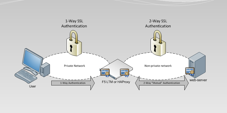
So a recent post I published talked about 1-Way vs 2-way SSL Authentication in some decent detail. We learned that 2-Way “Mutual” SSL Authentication can be used to enforce both parties attempting to communicate securely to provide authenticity. In other words, prove to each other that they are who they say they are. This can be very powerful from a security standpoint, but is it practical? The answer is, yes and no. The constraint comes from the aspect of administration (actually create certificates for each client) and manageability (keep accounting and maintaining actively lists of trusts) with the trade-off of proper authenticity. For example at first administering and managing 10 client certificates may be okay, but then imaging 100, or even a 1,000! So in this post I wanted to approach the idea of utilizing some tools we can use to offload some of this administration and management while maintaining Mutual Authentication with another entity. The idea revolves around one major assumption, users of a particular service (In this case a web-server) reside on a privately controlled and trusted network

My idea is if we have a group of clients residing on an internal privately addressed network, we can use either an F5 LTM or HAProxy to proxy our users’s connections destined for a service that is enforcing 2-Way SSL “Mutual” Authentication. The F5 LTM or HAProxy would perform the 2-Way SSL Mutual Authentication on behalf of each connecting user, eliminating the technical need to generate certificates for each client, while maintaining an element of mutual trust to the end service.

The basic idea is: (notice only our F5 LTM/HAproxy and the web-server perform 2-Way “Mutual” Authentication)

Continue reading…

TLS and mTLS authentication

Table of Contents

  1. About SSL Authentication
  2. Quick Review
  3. Creating a Certificate Authority
  4. 1-way “Standard” SSL Authentication
  5. 2-way “Mutual” SSL Authentication
  6. Advanced SSL Authentication: CRLs, CDP, and OCSP
  7. Concept Review

About SSL Authentication:

TLS Authentication or SSL authentication is nothing more than proving the authenticity of one or both parties in the formation of an TLS “Secure”  connection.

1-way “Standard” TLS Authentication is the most common, you use this every time you log into Facebook, your bank website, google, etc. The point of this type of authentication is for you (as the client) to verify the authenticity of the web site you are connecting to and form a secure channel of communication.

2-way “Mutual” mTLS Authentication is less common than the traditional “one-way” TLS authentication we are a custom to when visiting secured websites. When we connect to our banking website or our favorite web e-mail site, we as the client are verifying the identify of the site we are requesting content from. This “one-way” authentication allows us as the client to connect with confidence that the web site we are receiving content from has been verified. this authenticity check is performed by our client browser with a little help from a third-party certificate authority.

Let’s first review a one-way TLS connection.

  1. The Client browsers receives https://google.com in it’s address barf
  2. Client browsers knows based on https:// that this connection will require an SSL handshake and sends a CLIENT_HELLO to the destined web server (google). This includes other things like SSL/TLS version, acceptable ciphers, etc
  3. The web server receives the CLIENT_HELLO request and sends a SERVER_HELLO back to the client. SERVER_HELLO contains SSL version, acceptable ciphers, and the server certificate.
  4. The client receives the servers certificate and it is verified against a list of known Certificate Authorities.
  5. If the certificate is proven to be in good standing, the client sends back a pre-master secret is encrypted inside the server’s certificate. Remember only the server can decrypt anything encrypted with it’s certificate because only the server has the decryption key. Server Certificate encrypts, Server Key decrypt’s.
  6. At this point both client and server have the pre-master secret and can calculate a master secret to use to symmetrically encrypt and decrypt data between them.

So as we can see from a traditional TLS handshake, the client is never verified as authentic. Now, in most situations this is fine, as most connect types of this nature only need to verify the server because that is where the content is coming from.

The difference: In a 2-way mutual authenticated TLS handshake, the server will ask the client to send its own certificate for verification. Just like the client asking for the server’s certificate in the 1-way TLS handshake above, the server will perform verification of the client certificate before continuing to the pre-master and master secret phase of the SSL handshake. If authenticity of the client cannot be verified the server closes the connection.

How is mutual trust obtained? Both the server and client must generate their own TLS certificate and keys, and both must be signed by the same Certificate Authority. This ensures that both the server and the client’s certificate are trusted. This allows authentication to remain asymmetrical, instead of symmetrical. For example, rather than have a shared password that 3 clients and the server use to encrypt and decrypt data. Each client and the server have their own certificates and keys that will be used for communication with the server. Asymmetrical authentication and encryption is better at enforcing authenticity because everyone has their own cert and key used to establish a secure connection with the server. Symmetrical authentication is faster at encrypting and decrypting but suffers from having every client use the same key.

What happens if a client key is compromised? In the symmetrical authentication scenario, mentioned previously, you would have a serious security issue on your hands. Each client would be at risk and the likely hood of eavesdropping would increase. An attacker only has to obtain one key to gain visibility into every connection. Asymmetrical on the other hand has a different way of handling this. Because each client has it’s own certificate and key pair, and the signing of each certificate is performed by a third-party Certificate Authority, one simply has to revoke the compromised client in the form of a CRL certificate(more on this later). Other client connections will not be compromised or have to be re-generated. The server verifying the client certificate will fail only for the revoked for the compromised client.

What happens if my Certificate Authority’s key is compromised? This is the worst case scenario that can happen in your PKI infrastructure.An attacker can impose and generate a new certificate authority certificate and start signing certificates that can be used to fake authenticity. In essence break the certificate authority’s trust.  Keep in mind a Certificate Authority key cannot decrypt your connections.

Continue reading…

CiscoASA — AnyConnect SSL VPN Setup

As promised here is my article on how to setup a SSL remote VPN, an alternative to IPSec Remote VPN from this article. What’s great is the steps to setup an SSL remote VPN service are very similar to IPSec remote VPN!! So let’s get started.

As with IPSec remote VPN we will need similar design considerations for SSL remote VPN.

  • First, a subnet is required for client’s to be put on when successfully authenticated and authorized via the SSL remote VPN. This can be the same subnet as one already existing on your network or a separate one with a firewall in-between The later being best in practice and security.
  • Secondly, deciding on split-tunneling vs all-tunneling. The difference being on the client would you like all traffic to be forced across the tunnel or allow clients to communicate with both their local network and the networks on the otherside of the VPN. For best practice and security, all-tunneling is recommended.
  • Third, Access Lists and tunneled networks. Here we will decided what SSL remote VPN users will have have access to in our other networks. We will also, in the case of split-tunneling, create an access-list of what networks to tunnel for the Remote VPN user.
  • Fourth, provisioning standard network services for VPN user’s. Remote VPN user’s will need a default gateway, DNS servers, domain suffix, an address pool, proxy settings, etc.

Continue reading…

What is NAT-Traversal??

Hi All, been awhile since my last post, however I believe this to be a good one!. So…the question arose the other day regarding NAT-Traversal. What is that? Why do we have it? What does it do? Most network engineers have heard of NAT-traversal before when configuring their Firewalls and VPN Clients, etc. But, I wanted to take a minute to explain where NAT-Traversals (NAT-T) need came from and the reason we still use it.

In order to understand NAT-Traversal, we need to understand two Networking concepts. First we need to understand “The Network Flow”. HOw do two hosts on a Network maintain a communication session. The second, is Network Address Translation. Yes NAT’ing, is a big part of IPv4 networks, they are so common place that you are probably using NAT’ing right now when reading this article.

The Network Flow.

So in a typical end-to-end connectivity the network traffic flow is maintained by 4 main parameters.

  1. Destination IP
  2. Destination Port
  3. Source IP
  4. Source Port

These 4 parameters provide a seamless flow of packets back and forth to each end-to-end device within a communication. It is how packets carrying your data arrive at their destination and it is how a return response knows how to get back to the requesting device. The IP requirement is usually pretty straight forward, it’s like the address of a house. You have to know the TO and FROM fields when sending a mail letter. So where does this port information come into play?? So Port number is like a sub-address of where the mailbox is located on a house. Usually a home will only have one mailbox, but imagine the same scenario with an apartment building or housing complex..Many mailboxes at a single address. Now depending on where you live you may need to prepend or add a apartment number to the address. Translate this same concept to port numbers. If my address is 123 North St and I am sending to 789 South St. My courier knows how to drive to each destination, but it doesn’t know where to put the actual mail envelopes since it is an apartment building with hundreds of apartments. This is where the port number comes in. So if on my envelope I put 123 North St. Apt#100 and I am sending to 789 South St. Apt#201. My mail will be delivered not only to the correct address but the correct mailbox.

I like using the apartment analogy, because it makes us think about Address and Ports being used together to deliver mail. An address and port combination is called a Socket in the networking world.

Now in a typical request scenario, a client forms the TCP/IP datagram. A Client’s machine fills in the destination IP and Destination Port based on the target and application type generating the request. For example, when you type http:// in your browser, the browser application knows to use port 80 as the Destination Port. The client then fills in it’s own IP address for the Source IP, and the OS chooses a Source Port at random. We call this random Source Port, the Ephemeral Port.

A typical TCP/IP communication header.

Sent Packet:

Dst IP Dst Port Src IP Src Port
192.168.10.10 80 192.168.1.100 49152

Return Packet:

Dst IP Dst Port Src IP Src Port
192.168.1.100 49152 192.168.10.10 80

Continue reading…

F5 BIGIP — Configuring the F5 AOM (Always On Management) interface

The F5’s AOM (Always On Management) interface module is one of the fundamental administrative features offered by BIGIP appliances. If you are familiar with System or Blade management devices, it is the similar to ILO (Integrated Lights Out), with a few extra features. One of the features that I like about the AOM is its integrated menu that can be called up in the console at anytime by pressing ( This is helpful in situations where a bad image or upgrade has corrupted the base OS, making it difficult to reboot the appliance via the CLI.

SSH to the F5 Appliance and get onto the AOM adapter:

SSH to your F5 Appliance using an username with TMSH access and gain bash access by running…

user@(ltm01)(cfg-sync In Sync)(Active)(/Common)(tmos)# run /util bash

Under bash, SSH to the AOM adapter

[user@ltm01:Active:IN Sync] ~ # ssh aom

You are now connected to the AOM adapter. Now we need to configure the adapter:

root@ltm01:~# netconfig
AOM Linux Management Network Configuration
Use DHCP for ipv4?                      no
Host name(optional):                    ltm01-aom
IPv4 or IPv6 address (required):        10.0.0.2
Network mask (required):                255.255.255.0
Broadcast IP address (optional:
Default gatewahy IP address (optional): 10.0.0.1
Nameserver IP address (optional):

NOTICE: We needed to connect to the AOM adapter via ssh aom because no IP was set. Now you can SSH directly to the IP we just assigned the AOM module!!
Continue reading…