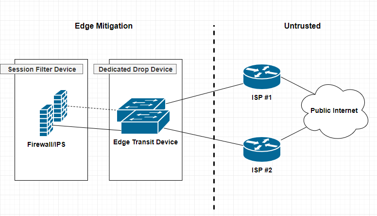
A dedicated drop device is a network appliance, usually a router or L3 switch that sites at the very edge of your network infrastructure. Beyond the firewall, and usually acts a as either layer 2 or 3 transit devices for your ISP interconnect uplinks for public or untrusted segments. Distinguishing a dedicated drop devices in your infrastructure interconnected chain of paths can enhance and offload many irrelevant packet transactions from ever hitting your Firewall mitigation appliances. The thought around this approach is to remove processing cycles away from your more expensive security appliances such as firewalls or IPS, allowing said devices to dedicate their efforts toward more complicated session and/or application driven attacks.
I’ve recently posted two articles covering two different VPN connection methods. SSL Remote VPN and IPSec Remote VPN via Cisco ASA security applicance. In the article I promised I would go thru and do a deteail compare and contrast of them. So Let’s get start!!
As promised here is the follow up post I mentioned here regarding setting up an Cisco AnyConnect remote access. Luckly the process is very similar to a remote access IPSec tunnel in the previous article with a few exceptions. Lets work through the differences between Cisco AnyConnect and a standard remote access IPSec Client VPN.
Comparison
SSL Remote VPN
IPSec Remote VPN
Cost
$$ per Connection, SSL certificate costs
Usually none, no SSL certificate costs
Capacity
Seats limited to licensing
Limited to Crypto Hardware
Performance
SSL with DTLS = Very Fast
IPsec without NAT-T = fast
Vulnerability
SSL vulnerabilties released frequently
IPSec requires pre-shared key
Requirements
SSL requires TCP 443, DTLS requires UDP 443
IPSec requires IP Protcol 50 (ESP) and UDP 500(IKEv1), NAT-T requires UDP 4500
Connection Considerations
SSL requires TCP 443 outbound for clients
IPSec requires both Layer 3 and Layer 4 protocols
NOTE: The table here is a quick reference when comprising SSL remote VPN with IPSec remote VPN. There are many things to consider when choosing between the two. SSL VPN is newer than IPSec, however the answer on which is better is not so straight forward.
IPSec remote VPN utilizes a variety of protocols and ports to form a successful tunnel. If you remember from my article on IPSec and NAT-Traversal, port requirements are UDP 500 for IKEv1 exchange, IP Protocol 50 for ESP communication, and if negotiated UDP 4500 for NAT-T. Most of the time these ports and protocols will not be allowed access outbound to the Internet. For instance, many guest networks like hotels and conferences only allow web browsable ports, such as 80(HTTP) and 443(HTTPS) outbound. That is a lot of firewall exceptions to establish an IPSec remote VPN.
SSL remote VPN introduces many connection and scalability improvements, making remote VPN functionality easier for the end user. SSL remote VPN solves the IPSec issues of a opening ports to establish a VPN session. Remote users no longer connect differently depending on where they are nor do they need to know how they are connected to the Internet, no fancy ports need to be opened, no issues with NAT-Traversal, etc. SSL remote VPN uses a very common trusted port for communication TCP 443 (and UDP 443, more on that later). This port is 99% of the time open to communicate with the Internet web sites. Using a commonly allowed port eliminates the issues seen with IPSec when establishing a VPN.
The trade-off, SSL remote VPN communicates via SSL/TLS. As stated this requires TCP, which is a stateful transport protocol. The issue arises when you have a remote host operating an application that uses TCP as well, such as web browser or Remote Desktop Connection. The scenario is now TCP on top of TCP, resulting in heavy overhead. Imaging the following scenario, you have a SSL remote VPN host connected, they then open a RDP session to a server on your network. So far so good. Now what happens when either the RDP session or the SSL remote VPN session requires a re-transmission because of connectivity problems. TCP re-transmission storms. Both the VPN session and RDP session will require re-transmissions, generating heavy overhead. Now this is not to say that either session will not recover, cause they will unless the connection is completely severed, TCP will do its job. Datagram Transport Layer Security(DTLS) to the rescue!!!
Datagram Transport Layer Security (DTLS)
DTLS is the savior and its what makes SSL client VPNs a very competitive remote access VPN technology. DTLS was designed to secure traffic similar to TLS, but without having to rely so heavily on the underlying TCP transport. TLS relies on TCP to guarantee delivery in the event of message fragmentation, message reordering, and message loss. So getting ride of any one of those TCP features will break the TLS crypto logic. DTLS solution to these issues is as follows:
Message Fragmentation — Fragmentation occurs when a packet datagram is too large to fit within an MTU (usually 1500bytes’ish). Fragmentation is detected and handled by the transport technology (TCP/UDP). TCP has mechanisms built in to solve this while UDP does not. DTLS solves this issue by introducing its own fragmentation offset and length value in the DTLS message itself. This ensure that both ends of the communication are provided fragmentation information regardless of the underlying transport.
Message Reordering — Reordering occurs for several reasons, a common reason is delayed delivery of the underlying network. Reordering isn’t a huge issue for transport technologies like TCP because it uses sequence numbering to ensure the original data is reassembled properly. TLS requires the sequential delivery of packets to preform it’s crypto logic, meaning TLS needs the previous packet to be able to decrypt the next packet N+1. DTLS solves this by adding it’s own sequence numbering to the application, allowing it to not be dependent on the underlying transport technology.
Message Loss — Packet loss occurs when a packet in a data stream never reaches its destination in a certain period of time. Message loss is handled very similar to Message Recording. For TLS and it’s TCP transport, re-transmissions are triggered for lost packets when sequence numbering doesn’t compute correctly for a agreed upon window. DTLS fixes this by adding a simple re-transmission timer to it’s application logic, thereby allowing it to re-transmit packets without relying on the transport protocol.
Keep in mind that DTLS built-in functionality of these usually transport specific recovery mechanisms creates the need for additional RAM/memory on the server-side. Another cool fact is most of these “fixes” come from IPSec ESP technology! See RFC4347 for more information.
I wanted to put together a quick tutorial for setting up a Cisco ASA – AnyConnect with SSL/TLS. I’ve done it a few times and I always have to re-lookup each step and the order in which to do it, so why not make a quick post about it to remember!
Optional: Destroy Current Trustpoint
You will have to destroy or clear out the current trustpoint if it already exists. This must be done if you are going to re-generate the key, which is best practice when renewing a Certificate due to expiration or one that has been compromised.
asa01(conf)# no crypto ca trustpoint oldtrustpoint.trustpoint
It will warn you that it will destroy any certificates within the trustpoint.
Generate a Key
Here we start with the generation of our key, using 2048 bits. the key name can be anything you want, but I like call it by the service I will be putting it on, for my case for this tutorial is accessthejimmahknowscom.key
newtrustpoint.trustpoint — The name I gave to this trustpoint which will tie everything together.
subject-name— This command holds the distinguished name of the Certificate’s profile, see RFC3039
keypair — This is what key to pair the trustpoint with, we generated this in the previous step.
fqdn — This is the main FQDN of our service that will use the trustpoint
enrolment terminal — This tells the Cisco ASA to output the CSR (which we will create in the next step) to the terminal screen. Otherwise you will have to SFTP to the ASA and download it.
As promised here is my article on how to setup a SSL remote VPN, an alternative to IPSec Remote VPN from this article. What’s great is the steps to setup an SSL remote VPN service are very similar to IPSec remote VPN!! So let’s get started.
As with IPSec remote VPN we will need similar design considerations for SSL remote VPN.
First, a subnet is required for client’s to be put on when successfully authenticated and authorized via the SSL remote VPN. This can be the same subnet as one already existing on your network or a separate one with a firewall in-between The later being best in practice and security.
Secondly, deciding on split-tunneling vs all-tunneling. The difference being on the client would you like all traffic to be forced across the tunnel or allow clients to communicate with both their local network and the networks on the otherside of the VPN. For best practice and security, all-tunneling is recommended.
Third, Access Lists and tunneled networks. Here we will decided what SSL remote VPN users will have have access to in our other networks. We will also, in the case of split-tunneling, create an access-list of what networks to tunnel for the Remote VPN user.
Fourth, provisioning standard network services for VPN user’s. Remote VPN user’s will need a default gateway, DNS servers, domain suffix, an address pool, proxy settings, etc.
I’ve posted an article on Client VPN setup using OpenVPN and I noticed I didn’t have one regarding Cisco ASA. A Cisco ASA being a very common Security Appliance used by small and large companies. This article will cover how to setup a standard remote client VPN utilizing IPsec as the crypto carrier. Cisco also has their own proprietary remote client VPN solution called AnyConnect. I will be posting an article after this one on how to set an AnyConnect solution up and include what the differences are between it and the standard IPsec remote client VPN contained in this article.
A remote client VPN is something very common in workplace now-a-days. It allows users to appear as if they are on the company’s internal network over an insecure medium(e.g. Internet, untrused Network, etc). It does so by using IPsec. IPsec is a tried and true Layer 3 securing technique that requires both parties involved to mutually authenticate each other before passing traffic.
A few things to keep in mind regarding remote client VPNs.
First, a subnet is required for client’s to be put on when successfully authenticated and authorized via the remote client VPN. This can be the same subnet as one already existing on your network or a separate one with a firewall in-between The later being best in practice and security.
Secondly, deciding on split-tunneling vs all-tunneling. The difference being on the client would you like all traffic to be forced across the tunnel or allow clients to communicate with both their local network and the networks on the otherside of the VPN. For best practice and security, all-tunneling is recommended.
Third, Access Lists and tunneled networks. Here we will decided what Remote VPN users will have access to other networks. We will also, in the case of split-tunneling, create an access-list of what networks to tunnel for the Remote VPN user.
Fourth, provisioning standard network services for VPN user’s. Remote VPN user’s will need a default gateway, DNS servers, domain suffix, an address pool, proxy settings, etc.
I’ve posted a few articles on how to set up a Forwarding Proxy using Squid, and using benefits like caching and content blocking (Ads, adult, gambling, etc). This can bring centralized web security and delivery to you and your users. However, users need to be expliclty configured to use the Proxy service. This means having their web browser like Firefox or even Internet Explorer set with the DNS or IP address of the Proxy server. This can be an issue if youhave little or no management of the user’s Web Browsers configuration. This is where a content-routing protocol like WCCP(Web Cache Communication Protocol) comes into play. With WCCP we can influence specific user traffic to be encapsulated and re-routed to your Proxy server. The difference between this and some of the other ways to force web traffic to your Proxy server(like iptables redirection) is the original Web packet generated by the user’s device is not altered. Instead it is encapsulated when it reaches your WCCP receiver running on an upstream egress router(user gateway towards Internet). It is then re-routed via this encapsulation to your Proxy server which is WCCP aware.
Before we begin, you will need a few things:
Squid Proxy Server 3.4+ compiled with WCCP
Router or Security device capable of running the WCCPv2 service(See vendor list here…)
Some knowledge of Web Proxy Technology.
A Web Browser to test with.
Your favorite beverage and some patients.
Topology
Notice: Cisco ASA only supports having the user subnet(s) and the cache-engine(Squid Proxy server) behind the same Cisco ASA interface(inside,dmz,outside,etc). The reason for this is the WCCP processing on the ASA happens after interface ACL, meaning for example ACL on your inside interface are processed before any WCCP manipulation can begin.
User requests a web resource on outside interface(usually the Internet) of Router/Firewall.
WCCP Server (Router/Firewall) catches this interesting traffic(traffic we want to redirect) and encapsulates it within a GRE tunnel to the WCCP Client(Squid Proxy Server) on the other end of the tunnel.
WCCP Client (Squid Proxy Server) decapsulates the GRE payload and fetches the original client request just like an ordinary Web Proxy would.
WCCP Client receives a response from the external web server.
WCCP Client (Squid Proxy Server) serves the web page back to the original User by spoofing the source IP address(This is key). Spoofing is done by rewriting the source IP address field of the packet with the External Resource’s IP address. This makes it look like the packet the user receives is from the external web site.
Hi All, been awhile since my last post, however I believe this to be a good one!. So…the question arose the other day regarding NAT-Traversal. What is that? Why do we have it? What does it do? Most network engineers have heard of NAT-traversal before when configuring their Firewalls and VPN Clients, etc. But, I wanted to take a minute to explain where NAT-Traversals (NAT-T) need came from and the reason we still use it.
In order to understand NAT-Traversal, we need to understand two Networking concepts. First we need to understand “The Network Flow”. HOw do two hosts on a Network maintain a communication session. The second, is Network Address Translation. Yes NAT’ing, is a big part of IPv4 networks, they are so common place that you are probably using NAT’ing right now when reading this article.
The Network Flow.
So in a typical end-to-end connectivity the network traffic flow is maintained by 4 main parameters.
Destination IP
Destination Port
Source IP
Source Port
These 4 parameters provide a seamless flow of packets back and forth to each end-to-end device within a communication. It is how packets carrying your data arrive at their destination and it is how a return response knows how to get back to the requesting device. The IP requirement is usually pretty straight forward, it’s like the address of a house. You have to know the TO and FROM fields when sending a mail letter. So where does this port information come into play?? So Port number is like a sub-address of where the mailbox is located on a house. Usually a home will only have one mailbox, but imagine the same scenario with an apartment building or housing complex..Many mailboxes at a single address. Now depending on where you live you may need to prepend or add a apartment number to the address. Translate this same concept to port numbers. If my address is 123 North St and I am sending to 789 South St. My courier knows how to drive to each destination, but it doesn’t know where to put the actual mail envelopes since it is an apartment building with hundreds of apartments. This is where the port number comes in. So if on my envelope I put 123 North St. Apt#100 and I am sending to 789 South St. Apt#201. My mail will be delivered not only to the correct address but the correct mailbox.
I like using the apartment analogy, because it makes us think about Address and Ports being used together to deliver mail. An address and port combination is called a Socket in the networking world.
Now in a typical request scenario, a client forms the TCP/IP datagram. A Client’s machine fills in the destination IP and Destination Port based on the target and application type generating the request. For example, when you type http:// in your browser, the browser application knows to use port 80 as the Destination Port. The client then fills in it’s own IP address for the Source IP, and the OS chooses a Source Port at random. We call this random Source Port, the Ephemeral Port.
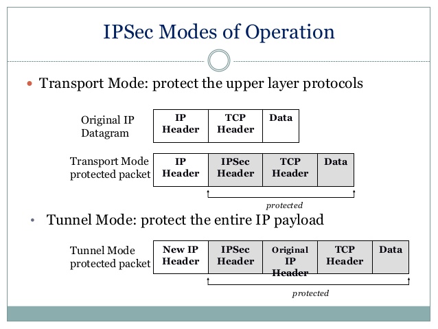
Most of the time when we are trying to establish a site-to-site or LAN-to-LAN connectivity between two independent parties over an untrusted medium we rely on IPsec. Internet Protocol Security (IPSec) is a open standard suite of protocols used to authenticate and encrypt IP Packets in a connection. This ensures data integrity and data confidentiality. IPsec can be used in a variety of ways, to secure host-to-host communication, network-to-network communication, host-to-network. The most common type is network-to-network. An argument can be made that host-to-host is the same as network-to-network with /32s (i.e. 192.168.1.1/32 to 192.168.255.1/32). Anyway!
IPsec allows us to form a secure virtual communication link over a untrusted medium such as the internet to allow LAN to LAN communication. Sound familar? VPN anyone? For instance if CompanyA with 192.168.1.0/24 address space and CompanyB with 172.16.1.0/24 address space require hosts on each of their networks to talk to one another, this can be accomplished by utilizing a IPsec tunnel. Hosts at CompanyA would be able to traverse the IPsec tunnel to CompanyB as it appears to them to be nothing more than another routed LAN. It’s a cheap and easy way to create this linked infrastructure without the need to buy or lay-down physically dedicate cabling. Why not piggy back and on an already existing insecure circuit and make it secure with IPSec!!
Phase 1 and Phase 2 ???
“Phase 1” — Before IPsec can even begin to send your data, there is a negotiation and the establishment of an agreed upon method to create and secure this connection. The negotiation is performed by Internet Key Exchange (IKE), which consists of (I think) 3 different Key Management protocols. ISAKMP, Oakley, SKEME. All of which are used based on how you want to setup the key exchange, ISAKMP being the most popular. The main point of this Phase 1 is two things, one to agree upon a way to protect this negoitation, followed by authenticating each endpoint to form a trust relationship. This all happens bidirectionally. Once both of those have been completed we have a successfully formed a IKE Security Association(SA) that maintains this trust. IKE uses the key exchange algorithm called Diffie-Hellman to establish a secret key between each end. After this secure channel is setup it will be used in the next phase to negotiate the IPsec SAs, creatively called “Phase 2”. Keep in mind thata single Phase 1 SA can house multiple IPSec SAs!!!, unless you are using Perfect Forward Security(PFS). PFS make it so each IPSec tunnel has only 1 unique Phase 1 SA, that way if Phase 1 is ever compromised it won’t jeopardize all your IPSec tunnels under a single Phase 1 SA. Did I lose you? 🙂
“Phase 2” — IKE is used to negotiate IPSec SAs and how IPSec should be protected. In this Security Association (SA), the actual networks at each end of the tunnel must be agree upon. If they are not, Phase 2 will never come up as their SA are in mismatch. Furthermore, in this Phase 2 an agree upon Transform-set is established. The Transform-Set is the method on how the packets will be encrypted and transmitted out the tunnel interface. How should we transform the packets through the tunnel?Phase 2 also uses the key exchanged from Phase 1 to be used when encrypting the data. If PFS is used, keys are derived independently and not from Phase 1. The cost being time, benefit being a single key compromise does not compromise all IPSec tunnels. Keep in mind Phase 2 is required to be completed at both ends. If not the opposing side won’t know how to decrypt the data!!
So in summary IKE is used to protect Phase 1 and Phase 2, IPSec is used to send the packets. If you want to understand these steps further, I recommned reading this overview. It is a great explaination. Also if you haven’t already bookmark PacketLife.net!!
Openswan U2.6.37/K3.2.0-4-amd64 w/NetKey Support connecting to a Cisco ASA 5505 running version 9.1(3). I include the versioning because I read a lot of articles where the version of OpenSwan matters tremendously, and also seems to influence what types of issues you might run into. The version I am running uses a fairly new feature called NetKey. From my research this was introduced to make configuring a IPSEC tunnel easier and not require the re-compiling of the Linux Kernel. Continue reading…
Hi Folks! So I was trying to update my Cisco ASA 5505 my buddy gave me from version 8.2 to 9.1. However upon reloading the device with the new 9.1 image file I got a warning on the console! I received the error of purchase Cisco item “ASA5505-MEM-512=”
I was trying to set up a SOHO router for a small client the other day and was having difficulty getting the DNS server to function the way I wanted on the router. I could get the DNS server to run on the Cisco Router, but it would only work on external domains. Any static record I added would not be resolvable for clients.
For starters, I will assume you have your own Cisco router running 12.4+ IOS firmware with ipservices.
DHCP first…
First, let’s set up DHCP on the Router
R1(config)# interface fastEthernet 0/1
R1(config)# ip address 10.0.0.1 255.255.255.0
R1(config)# no shutdown