F5

F5 BIGIP — iRules….What are they?

What is an iRule? What are iRules? What can I do with iRules? What is an iRule example?

One of the most advantageous features that an BIG IP F5 Local Traffic Manager brings is it’s iRule feature. This feature allows the F5 to manipulate and perform event driven functions to the application traffic as it passes through the F5 LTM. This is very useful and has many use cases. For example, a common iRule is as follows. Let’s say you have a typical load balancing setup, with 5 web servers being balanced in a round robin fashion. The traffic that passes through is HTTP. For security purposes only HTTP-SSL is allowed to this site, however you don’t want users to have to remember to put https:// rather than http:// in their internet browser’s address bar. Instead of putting a redirect page on the port 80(insecure) instance on each of the 5 web servers, a simple iRule will take care of that!

Example HTTP to HTTPS redirect iRule:

#my first iRule 
when HTTP_REQUEST { 
    HTTP::redirect "https://[HTTP::host][HTTP::uri]" 
}

When we look at this iRule we see a few things. We see an event that must be triggered in order to for the iRule to execute, “when HTTP_REQUEST“. Next we see a HTTP redirect function being performed with a few parameters. HTTP::redirect is the function and the target URL string “https://[HTTP::host][HTTP::uri]”. Let’s break this statement down as it is the meat and potatoes of the iRule.

https:// is what protocol to send the users browser when it performs the redirect.

[HTTP::host] which is derived from the clients host-header as it comes across to the F5 LTM. The host header is set when you open a new browser and type the domain/host you are requesting to go to. For example, if you type http://www.google.com in your browser, when you hit enter in the HTTP stream the host-header is set to www.google.com. This is essential when using SSL, but more on that in another post.

[HTTP::uri] the last part is the URI the user is trying to GET. If this is a standalone site such as www.mysite.com, usually users will hit that first and be redirect already via our iRule before they browse to any URIs. However, perhaps a user tries to go to http://yousite.com/URI, they are not coming across HTTPS so the iRule will intercept it and redirect them to https://yoursite.com, but wait we don’t want them to get kicked back to the root of the site, so the [HTTP::uri] is appended to the redirect target string.

URIs vs URLs:
You will see people use these interchangeably, or used in-properly. Even Wikipedia’s article on them is confusing. A URI is what is appended at the end of the host or FQDN, and a URL is the whole thing.

So,
http://en.wikipedia.org/wiki/Computer

FQDN = en.wikipedia.org
URI = wiki/Computer
URL = http://en.wikipedia.org/wiki/Computer
What is BIGIP F5 (LTM and GTM)?

I’ve worked with BIGIP F5 hardware for over two years now, and have become quite familiar with the great features it provides. For those who are unfamiliar with BIGIP F5 hardware, it is network hardware company specializing in load balancing at both the local and global layers of an enterprises network infrastructure. Their website is located here.

BIGIP F5 product family consists of many different components, however the two major ones most network engineers are familiar with are the Local Traffic Manager(LTM) and the Global Traffic Manager(GTM). Both are network rackable load balancers.

The GTM

is used as an “Intelligent DNS” server, handling DNS resolutions based on intelligent monitors and F5’s own iQuery protocol used to communicate with other BIGIP F5 devices. Seen at the top level of a data center, especially in multiple data center infrastructures, deciding where to resolve requesting traffic to. The GTM also includes other advanced features, such as DNSSEC and intelligent resolution based on many different algorithms.

The LTM

is a full reverse proxy, handling connections from clients. The F5 LTM uses Virtual Services(VSs) and Virtual IPs(VIPs) to configure a load balancing setup for a service. LTMs can handle load balancing in two ways, first way is a nPathconfiguration, and second is a Secure Network Address Translation(SNAT) method.

nPath, the F5 does the job of load balancing by intelligently deciding which server endpoint to pass traffic to. nPath, however, does so by bypassing the F5 in the return path. For example you have two servers 192.168.0.10 and 192.168.0.11, and an F5 listening for this particular set up on VIP 172.16.0.2. Now when the traffic from a client destined for the 172.16.0.2 hits the F5, the F5 intelligently passes it to either 192.168.0.10 or 192.168.0.11. The tricky part is when the traffic leaves from the F5 to either server, the IP packet’s source address is that of the F5. Therefore each server mush have a loopback address configured that matches the F5s source IP address of the interface (on the F5) the original packet leaves from., in this example 172.16.0.2. This prevents each server endpoint from sending it back to the F5 directly and forces the server to use it’s gateway of last resort.

Secure Network Address Translation(SNAT), is a more common BIGIP F5 implementation. In this scenario the F5 is configured essentially as a reverse-proxy server. Think Many-to-One. Client’s target Virtual IPs that sit in front of a pool of endpoint servers. However, the Client never sees behind the VIP, to there perspective the VIP is the server they are requesting. For example, you have a VIP 192.168.0.55 which routes to an F5 who is listening for requests destined for that IP. The F5 has a configuration in place that knows 4 server endpoints that can serve requests destined for that IP, 10.0.0.5, 10.0.0.6, 10.0.0.6, 10.0.0.7. When a request comes from a client to the VIP the F5 acts as the server for the client. In the back-end the F5 acts as a client sending the identical request to one of the four endpoint servers. The response is then proxied back from the F5 to the “real” client.

Tying them together.

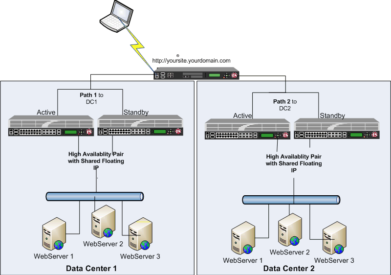
GTMs and LTMs used in conjunction with each other provide a robust and resilient, and network optimized environment. This is especially true when dealing with multiple Data Centers or Service Sites. The GTMs will handling the initially network path to take by resolving clients with the best route option. The LTMs will handle the load optimization of the service by logically proxying the endpoint servers.

Below is a diagram of a typical GTM/LTM setup. In this example, there are two Data Centers, the GTM sites at the front of the Data Centers and hands out the VIP that will handle the client’s request. The LTMs are localized in each Data Center (They don’t have to be :-p) in a High Availability pair. The LTMs will reverse proxy the clients connections with the actual server endpoint.