I set out on this home project with the intent of providing wireless internet to friends and family when visiting. I wanted to provide internet without allowing any malicious clients from consuming all my bandwidth and/or crippling my internal home network. There are many Wireless Access Points(WAP) that are capable of broadcasting multiple SSIDs. Cisco makes a few from their Aironet series, however they seem to be pretty expensive. I settled with a Netgear WNDR3700 after reading a few posts on hardforum.com that had success running OpenWRT.
OpenWRT is an third-party firmware designed for consumer based Access Points, such as Netgear, Linksys, Dlink, etc. OpenWRT adds many additional features, including the two features I needed. Support for 802.1Q trunking and gives the ability to run multiple SSID wireless signals.
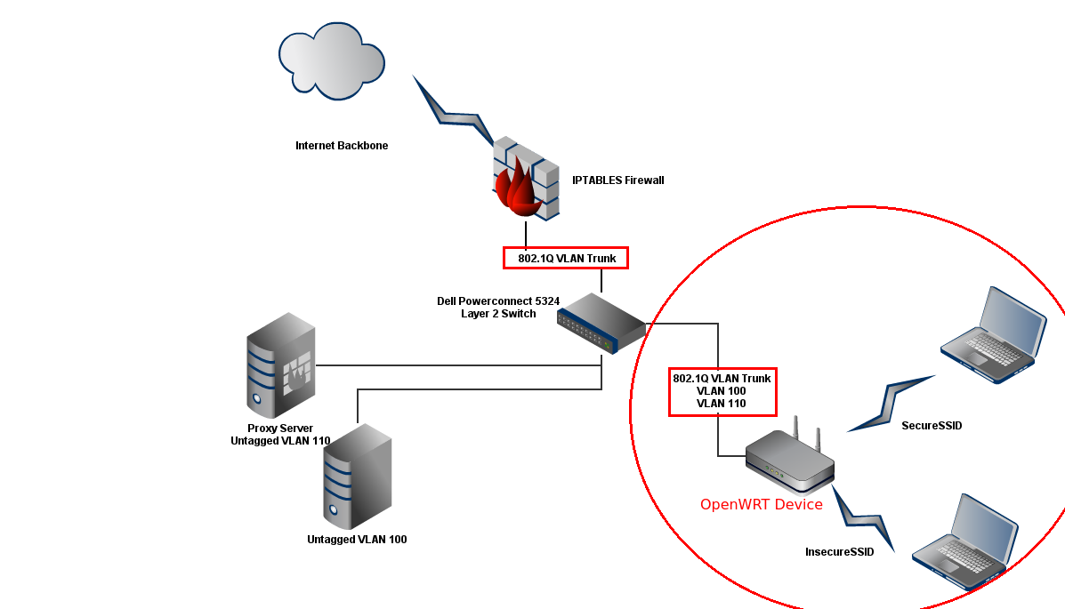
Topology

Installing OpenWRT
-
Download OpenWRT for Netgear WNDR3700
Visit the OpenWRT download site, here. Download the firmware image named openwrt-ar71xx-wndr3700-squashfs-factory.img
-
Upload firmware
Connect to the Netgear WNDR3700 using an Ethernet cable, the instructions for uploading the firmware warn against doing it over wireless.
-
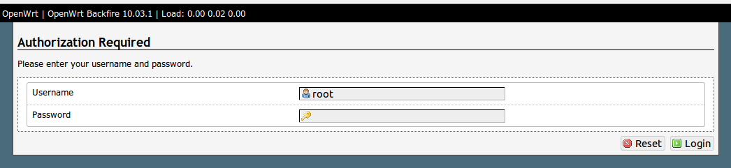
Verify firmware change
The only point of this step is to verify that the new firmware was a success. We changed the OS running from the factory Netgear firmware to OpenWRT. Visit http://192.168.1.1, you should say the following:
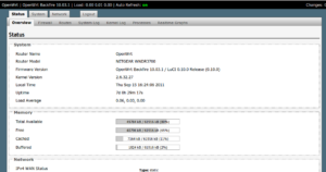
NOTICE: Verify the Firmware Version.

Configure OpenWRT
-
Configuring our 1st SSIDs
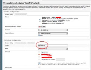
The two(2) SSIDs that we will be configuring will be named secureWiFi and insecureWiFi. To do this go to the Web Configuration page of the Netgear Router, http://192.168.1.1 (or whatever you have yours is IP’d for). Click on the main Network tab, and the WiFi subtab. This will list the following WiFi SSIDs defined. On a fresh firmware install it will be named OpenWRT and there should be only a single instance of it. Click Edit next to the OpenWRT SSID, change the name of the SSID to secureWiFi, then click Save & Apply.
-
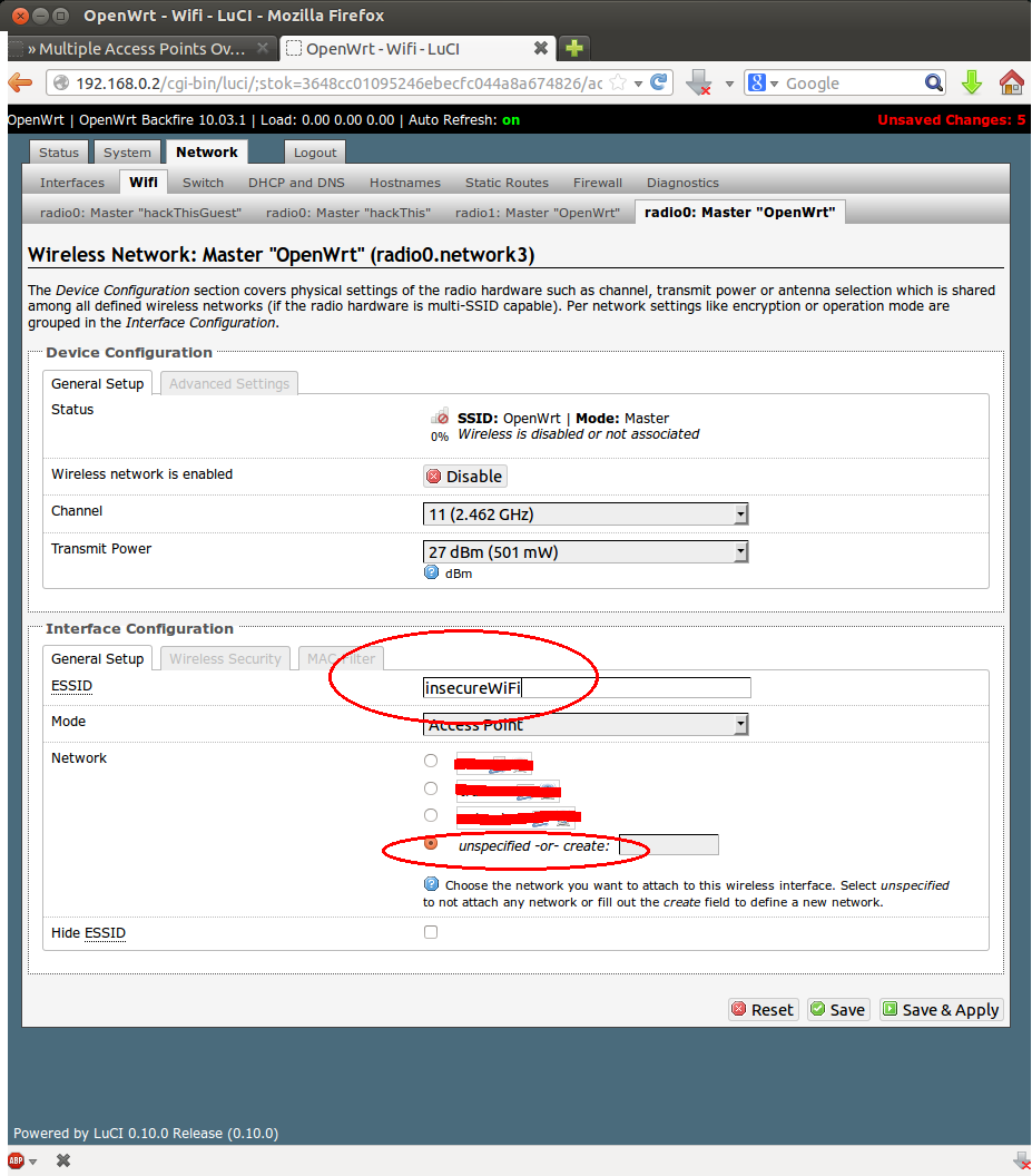
Configuring our 2nd SSID
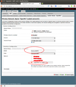
We will now add an additional SSID and name it insecureWiFi. On the Netgear Router’s page, go back to the Network tab and WiFi tab. Change the SSID name from OpenWRT to insecureWiFi.
-
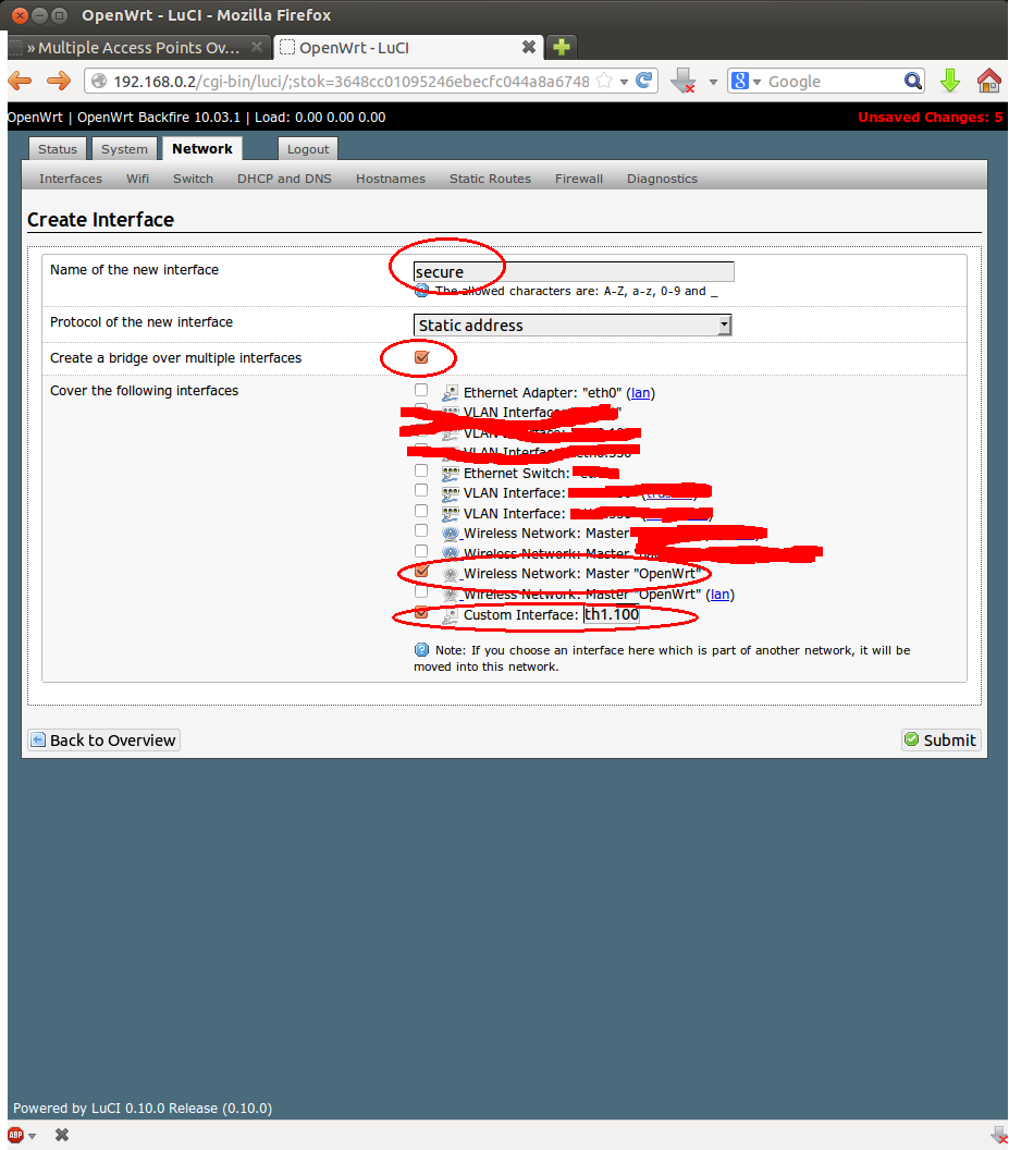
Configuring Interfaces in OpenWRT
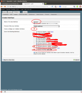
For the next part, we need to configure two separate interfaces on the OpenWRT router. These two separate interfaces will physically separate the two(2) different WiFi Access Points. We will need two separate IP network segemnets as well. For this article the two(2) IP networks will be 192.168.0.0/24 and 192.168.1.0/24. To do this, go to the Network tab, then the Interfaces subtab. Here there should already be one or two default interfaces. Click the button for Add New Interface(s). On the next page, Fill out the Name of the New Interface, “secure”. Check the box for “Create a bridge over multiple interfaces”. Under the section “Cover the following interfaces” Check of the Wireless Network “OpenWRT” or whatever you called yours that you would like to be associated with this “secure” interface” we are creating. The last part is to check the box for “Custom Interface” and add the label “eth1.100”. Now the eth1 is the physical interface of the WAN port, see diagram. The “.100” means add a virtual interface or VLAN interface with VLAN ID (VID) 100.
-
802.1Q Trunking
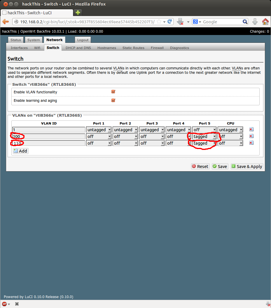
Now have to set the trunk port on the Netgear Access-point. Browse to the Network tab and then to the Switch subtab. Here You’ll see some information regrading the ports on the Netgear router and the VLAN IDs. With a new install there should be only VLAN ID 1 and it will be untagged on every port. This is the native VLAN, which pretty much means it is the only VLAN that will always be untagged for every interface, see here.
Ok so Click Add button to add a new row. In the new row that appears type in 100 in for the VLAN ID. Make sure every port number, except port 5 is off. Port 5 is tagged. Port 5 = WAN port on the back of the Netgear device. Perform this step again for our Guest/Insecure VLAN 110. Last step is to ensure the checkbox is checked for Enable VLAN Functionality.
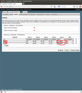
NOTICE: We have just created one end of a trunk link. The Netgear device will now tag Frames with VLAN ID 100 and 110 out Port5/WAN port.
-
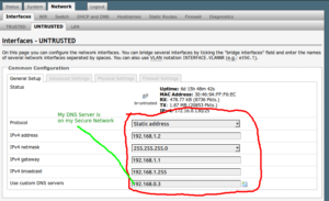
Optional: Set Device IP for Insecure Network
As of now we have successfully configured our Layer 2 network. However, if we were to connect to our Guest/Insecure network we would not be able to reach our Netgear device from an IP perspective. Meaning guests could not access the Netgear configuration page. This is only to make troubleshooting in the next section easier, you can remove it later if you are worried about security.
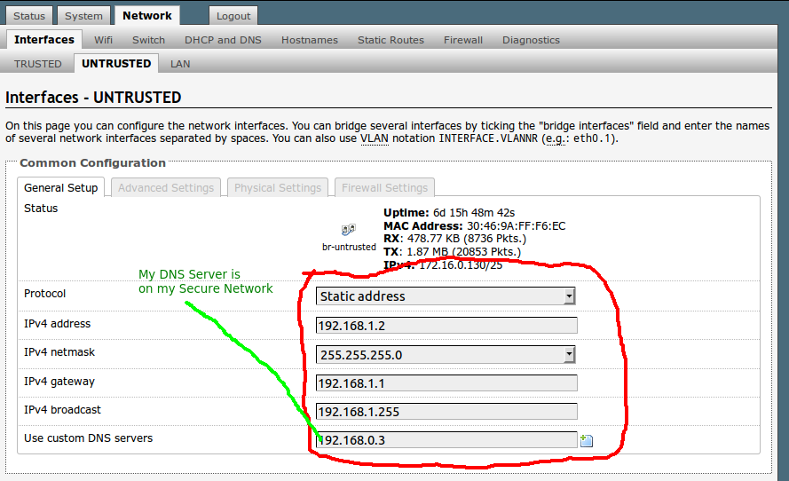
So browse to the Network Tab, then to the Interfaces subtab. Here you should see another subtab from earlier steps that shows our insecure interface. Click on that and there will be a Common Configuration section, with Status, Protocol, etc. Change the protocol to static address. There is an option for “Unmanaged” that would effectively mean that you cannot access the management part of the Netgear device through this interface. Fill in the IP information for our 192.168.1.0/24 network.
-
Save & Apply
Go ahead and hit the Save & Apply button.

Switch Configuration
-
Physical Configuration
On your VLAN capable switch, choose an interface that will be used as a trunk interface. For this tutorial I am using a PowerConnect 5324 with 24 Gigabit ports. I will be using port 20 for the trunk between our Netgear device and the PoweConnect switch. I also have another Trunk port, port 24 which is a trunk between my Linux Firewall and the PowerConnect switch.
Go ahead and plug in the WAN on the Netgear AP to the trunk port on the switch that you chose.
-
Configuring the Switch
Terminal into your switch. Now depending on what manufacture you have the commands may be a little different. But, really all we need to accomplish is add our two VLANs (100 & 110) to the VLAN database, and change the mode of the switch interface you picked to a trunk interface.
-
Adding to the VLAN Database
On the PowerConnect:
SW1 configure
SW1(config)vlan database
SW1(config-vlan)vlan 100
vlan 110
SW1(config-vlan) exit
SW1(config)
Assign VLAN Names:
SW1 configure
SW1(config) interface vlan 100<
W1(config-if) name SecureVLAN
SW1(config-if) exit
SW1(config) interface vlan 110
SW1(config-if) name InsecureVLAN
SW1(config-if) exit
SW1(config) exit
-
Assigning Trunk Ports
Using interface g20 as Trunk port
On the PowerConnect:
SW1 configure
SW1(config) interface ethernet g20
SW1(config-if) switchport mode trunk
 switchport trunk allowed 100
 switchport trunk allowed 110
-
Configuring Access VLAN Ports
Access Ports are interfaces that 99% of the time are connected directly to an end user device, such as a computer or server. Sometimes referred to untagged ports, etc. These next steps will be heavliy relative to your physical set up. For me, I know on my PowerConnect 24-port switch that ports 1-19 are secure and trusted. These ports go directly to network drops in my house so I know they are secure. The remaining ports 20-24 are untrusted and insecure, at least I left them open to be used that way. Remember Your Scenario May Be Different.
Assigning Access Ports on the PowerConnect:
SW1 configure
SW1(config) interface range ethernet g1-19
NOTICE: This allows me to configure multiple interfaces within a range.
SW1(config-if) switchport access vlan 100
NOTICE: We don't do the same thing for our guest network or insecure network. There is no point as none of my network drops in my house I want on the insecure network.
That's it for the first part!
We have a trunk link going from our PowerConnect Switch to our Netgear Access Point. Wahoo!

1 Response
[…] part 1, part […]