I recently purchased a 24-port Gigabit Layer 2 Switch that supports VLAN tagging and trunking. Dell PowerConnect 5324, see here, has 24 Ethernet ports and is capable of tagging and untagging Frames at wire speed. It is a discontinued model, however doing some googling I found a updated firmware and IOS image!
Physical Topology
The topology is pretty typical of “routing-on-a-stick” for Multiple VLANs. I have a Linux server running Ubuntu 12.04 with a single NIC and the Dell PowerConnect switch.
Port configuration:
Network 1 = g1 – g16
Network 2 = g17 -g23
802.1q Information:
Switch Trunk Port = g24
Router Trunk Port = eth1
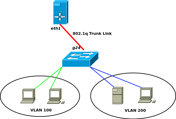
Logical Topology
I have a single LAN I want logically separated using a single switch. The VLAN IDs are 100 & 200. The VLAN subnets and ports will be as follows;
Subnets:
VLAN 100 = 192.168.1.1/24
VLAN 200 = 192.168.2.1/24
VLAN Access Ports:
VLAN 100 = g1 – g16
VLAN 200 = g17 -g23
Now before we continue with the configurations, I want to explain the differences between an Access Port and a Trunk Port when using VLANs. An access port is 99% of the time connected to an end user device, such as a computer, Wireless AP, etc. A trunk port, is connected between network devices and carries multiple VLAN tagged Frames. A trunk link is what makes this setup possible, carrying VLAN 100 & 200 Frames over one physical cable from the Linux Router to the Dell Switch.
There is also the terminology of Tagging and Untagging. Tagging referes to the 802.1q (or Cisco’s ISL) Ethernet tagging of Frames as they enter a Access Port. Untagged is the opposite, this refers process to untagg Frames as they leave an Access Port. The tagging and untagging is VLAN ID specific, meaning you can’t tag a Frame with VLAN ID 100 and have VLAN ID 200 untag it. Also, Tagged Frames cannot be sent to end user devices, as the end user device will not know how to read the Frame. For our example, g1-g16, and g17-g23 are Access ports. Maintain these VLAN ID and Interface Port associations happens on the Switch itself, why Managed Switches are able to support VLANs and unmanaged Switches do not.
When you run this command you are denoting a physical interface as an Access Port for VLAN 100, Frames leaving this interface will be Untagged from VLAN ID 100, and anything entering the interface tagged on VLAN ID 100.
console(config-if)# switchport access vlan 100 Here is TCPDUMP showing the 802.1q header in an Ethernet Frame:
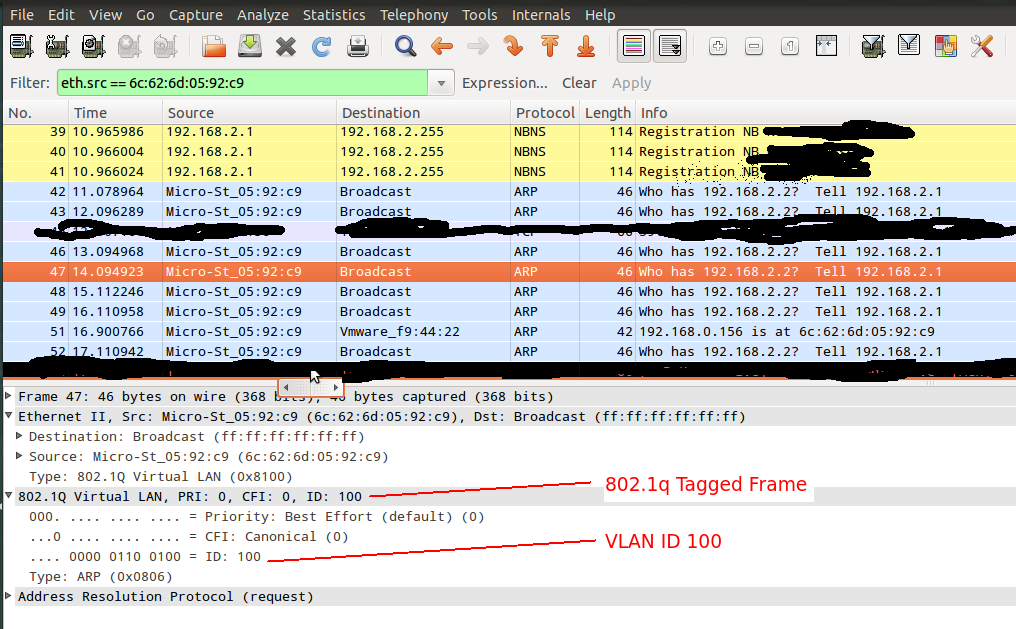
For more information on VLAN tagging see here.
Configure Switch
- Add VLANs to VLAN Database on Switch
console# configure
console(config)# vlan database
console(config-vlan)# vlan 100
console(config-vlan)# vlan 200
console# interface range ethernet g1,g2,g3,g4,g5,g6,g7,g8,g9,g10,g11,g12,g13,g14,g15,g16
console# switchport mode access
console# switchport access vlan 100
console# interface range ethernet g17,g18,g19,g20,g21,g22,g23
console# switchport mode access
console# switchport access vlan 200
- Verify VLANs
console# show vlan
Vlan Name Ports Type Authorization
---- ----------------- --------------------------- ------------ -------------
1 1 g(17-24),ch(1-8) other Required
100 Network1 g(1-16) permanent Required
200 Network2 permanent Required
- Set IP on Network 1 (VLAN 100)
console# configure
console(config)# interface vlan 100
console(config-if)# ip address 192.168.1.2 255.255.255.0
- Lastly, set Trunk interface and the allowed VLANs to egress the Trunk link:
console# configure
console# interface ethernet g24
console# switchport mode trunk
console# (config-if)# switchport trunk allowed vlan add all
NOTICE: The switch will spit back the current VLANs it knows about from it’s VLAN database. Therefore, if you add more VLANs to the database you will need to reissue this command to add the new VLANs to be allowed across the Trunk Link.
- Don’t forget to save!
console# copy startup-config running-config
Linux Router Configuration
- Install VLAN package
apt-get install vlans
- Add the 8021q module to be in the startup modules
modprobe 8021q
Add 8021q mod to the bottom of /etc/modules
vi /etc/modules
# /etc/modules: kernel modules to load at boot time.
#
# This file contains the names of kernel modules that should be loaded
# at boot time, one per line. Lines beginning with "# are ignored.

loop
lp
rtc
8021q
- Add VLANs to each Sub-Interfaces
vconfig add eth1 100
vconfig add eth1 500
NOTICE: The terminal will echo a information message telling you that eth1.100 and eth1.200 have been added. Run ifconfig and you’ll see them.
- Edit Network Interface Config
vi /etc/network/interfacesm auto eth1.100 iface eth1.100 inet static address 192.168.1.1 netmask 255.255.255.0 network 192.168.1.0 broadcast 192.168.1.255 vlan_raw_device eth1 auto eth1.200 iface eth1.200 inet static address 192.168.2.1 netmask 255.255.255. network 192.168.2.0 broadcast 192.168.2.255 vlan_raw_device eth1 - If you want the two networks to talk to each other you need to enable IP forwarding on the Linux Router
echo "1" > /proc/sys/net/ipv4/ip_forward
- For good measure. Restart eth1 on the Linux Router
/etc/init.d/networking restart
That’s It! The Linux Router is able to communicate with the Dell switch via an 802.1q Trunk Link.
How to Test
To test the VLANs are working and separating the Traffic based on the Access Ports, grab a Laptop and a Network cable. Configure your laptops local NIC to 192.168.1.5/24. plug the cable into your laptop and any one of the g1-g16 ports. Try to ping another device on that network, such as 192.168.1 or .2. It works! Now lets test to make sure the VLANs are separating traffic, using the same ip of 192.168.1.5/24 connect your laptop to any one fo the g17-g23 ports. Remember these ports are on a different LAN whos layer 3 network is 192.168.2.0/24(this really doesn’t matter because we are dealing with Layer 2 only). Try to ping a device on the 192.168.1.0/24 network. Hmm, doesn’t work….That’s a Good thing! The reason is the VLAN separation going on in the switch. When you tried to ping 192.168.1.1 from 192.168.1.5(laptop) an Layer 2 broadcast went out to all ports VLAN, in this case VLAN 200. The broadcast did not cross into VLAN 100 because of the logical separation.
A lot more is going on here, but is outside the scope of this article to be explained.
Sources:
- http://stevejenkins.com/blog/2011/05/dell-powerconnect-5324-setup-tasks/
- http://ubuntuforums.org/showthread.php?t=703387
- http://www.9tut.com/virtual-local-area-network-vlan-tutorial
- http://www.linuxjournal.com/article/10821?page=0,2
- Getting Started Wiki for Dell PowerConnect 5324
- Dell PowerConnect 5324 CLI Reference

DId you do some speed test? cpu consumption?
I want to switch 6 vlan with L2 Switches. I did with a Fortigate unit but transfer eat about 52 % of the firewall.
Unfortunetly I lab’d out this post two years ago and do no longer have any stats. It was a POC test so only a handful of devices.
If you do go along with testing out your 6 VLANs let me know!
GREAT explanation of multiple VLAN usage in a SOHO environment. And thanks for the link to my Dell 5324 article, too! I’m going to link back to this one from the bottom of mine, since I’m sure others will want to know how to do this. 🙂